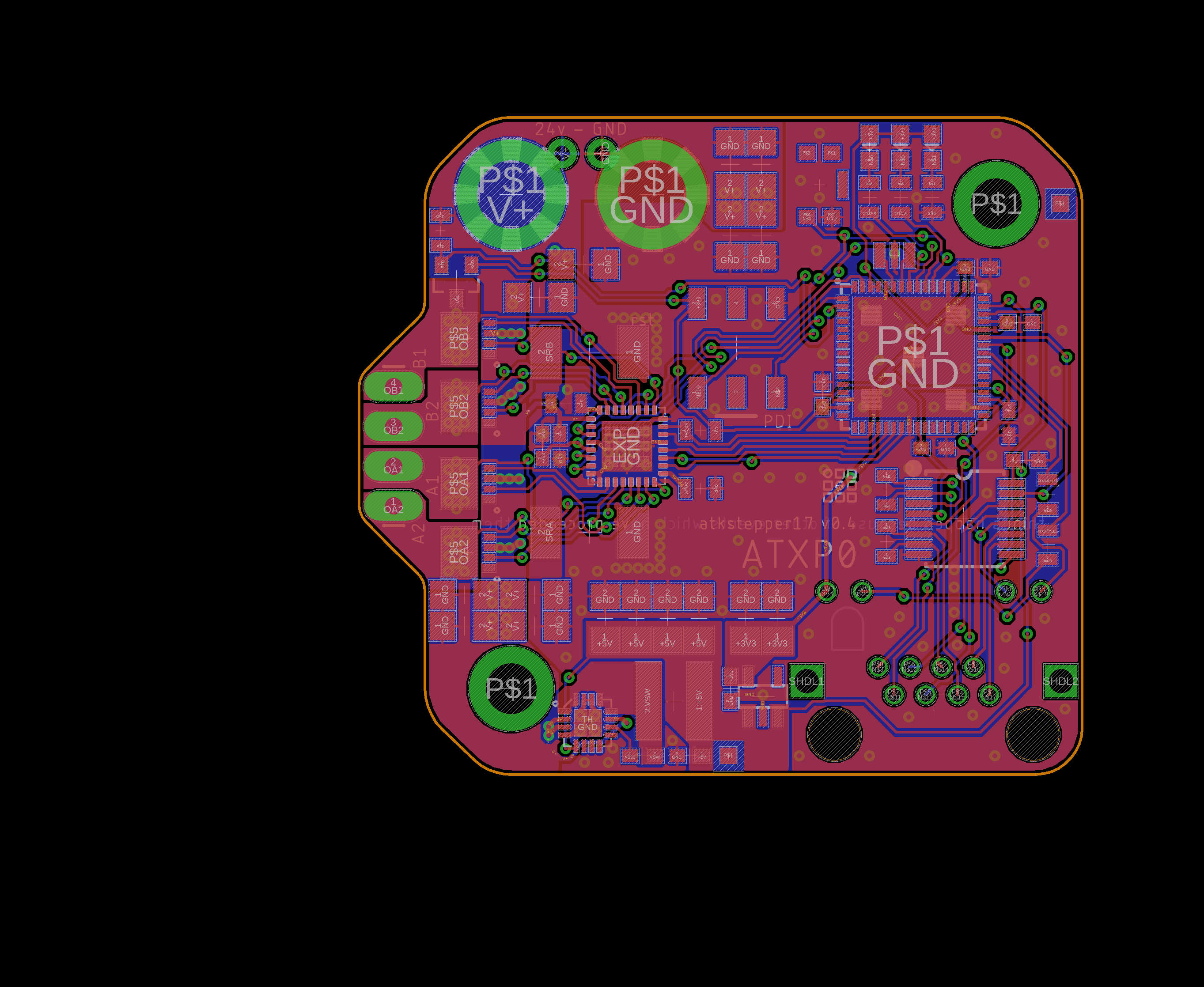
AutomataKit Stepper17 Circuit Design

The circuit uses an ATXmega256A3U microcontroller and a TMC2130 step driver to do the business. Between the two are an SPI bus, to configure the driver, two diagnosis lines, a step, direction, and enable lines.
The TMC2130 is a popular step driver, and can sink ~ 1.5A of current.
Power is bussed into the board with two M3 Screw Terminals. The board is not polarity protected. Data is delivered on an Automatakit Port, which includes a data line (uart TX / RX) and clock lines (CLKIN and CLKOUT)
Next Circuit
- on current scaling, get rid of PWM circuit and line out, use internal ref, and choose resistors with math: want 0.5 - 1.2A to be inside of 16-32 selection
- go to 2oz copper bc u fancy, etc
- get rid of this split gnd
-
- rtd
-
- as5047?
- fans? heatsinks?
- consider tmc262 and IRF9389TRPBFCT-ND , so that stepper code copy + pasta & hella N17 possibilities?
BOM
22nF 0.1uF 470nF 10uF
2R2 470R 1k 10k
Resonator LED Y,G,B RTD
SHNT 2520 PWRPAD 2x3 6PIN RJ45
RST BUTTON
XMEGA VREG-AP2112 RS-485-SN75C1168 TMC2130 AS5047D