DRV8436 breakout board
A tiny castellated carrier for the QFN version of TI's DRV8436 stepper driver.

As used in a circuit:
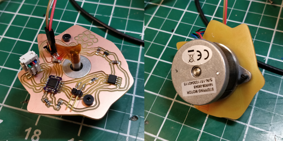
v0.1
The first version works, but has a dumb issue. You see, the DRV8436 has an internal voltage regulator which provides a logic-level power source so you only have to send it motor voltage. In an effort to minimize pin count, I decided to use that output to hold the nSleep pin high to keep the chip awake. However, the device checks nSleep before turning on the regulator, so as-is it doesn't wake up. For this version, the fix I included simply bridges the nSleep pin to M1, which I do break out as a castellation. M1 and M0 are used to configure microstepping; with this modification, the user must hold M1 high for the device to function, which limits them to 1/4, 1/8, or 1/16 microstepping only. Sorry friends.
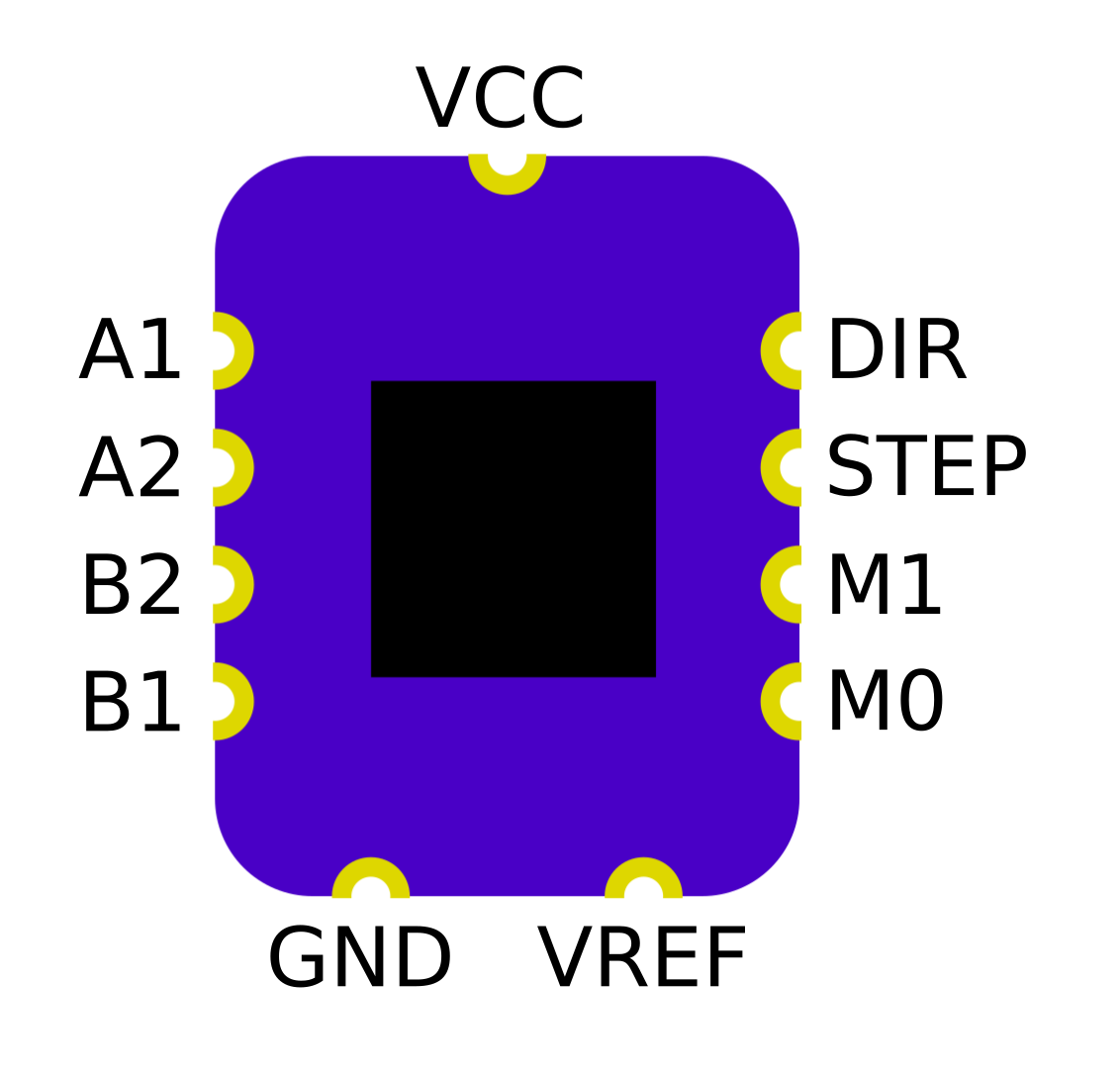
The board measures 9.5 mm tall and 7.5 mm wide. The four pads on either side are vertically centered and separated by 1.5 mm. The VCC pin is horizontally centered, while the GND and VREF pins are at +/- 1.75 mm. The design includes all of the recommended bypassing capacitors with the exception of a bulk tank cap, so it's a good idea to include a 33 or 47 uF capacitor between VCC and GND. You can supply the board with up to 12 VDC; some of the capacitors are 16 VDC units, so you shouldn't go much higher than that. Here is a sample schematic:
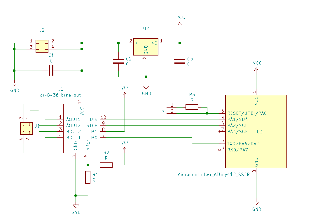
J1 connects to the stepper; J2 gets 12 VDC; J3 programs the ATtiny412; U2 is a 5 VDC regulator; C1 is a 33 uF ceramic cap; R1 and R2 are in the 5-20k range and used to set the current limit for the stepper. Again, note that M1 is held high to deal with the issue listed above.
To use the board in a project, you can use the KiCad schematic symbol and footprint file in the example_project directory, or you can make your own based on the image above. As always, it's worth reading through the chip's datasheet to understand how it works.